ZF-1 Assembly Tutorial - Page 4
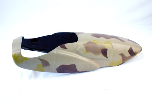
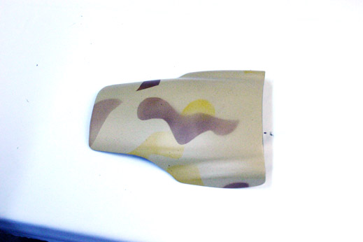
Bottom Shell Floor Mat
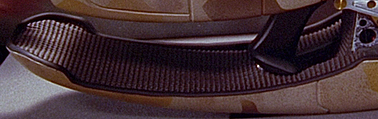
At this stage we'll add the Floor Mat material to the Bottom Shell. This Floor Mat adds aesthetic value to the finished prop. If you added the Floor Mat before this point in assembly, you might have noticed that it continuously captured drill shavings and debris through-out the assembly process.
For those readers just joining this tutorial, we are using the Superkrates "Mark II" ZF1 Kit for our ZF1 build.
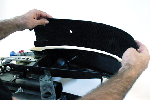
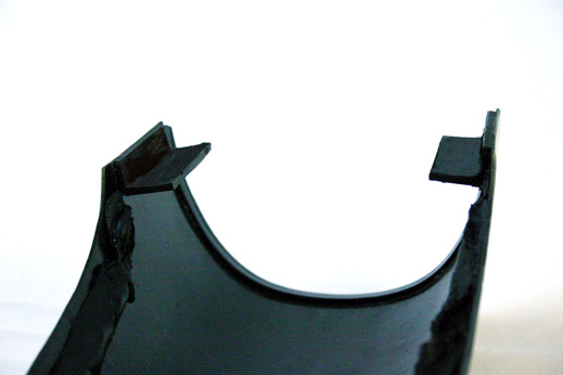
The Floor Mat, precut for assembly...
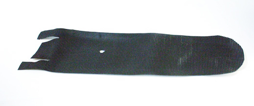
The two side 'tabs' are not needed with the Superkrates Mark III kit, as those tabs are replaced with parts from the Star Trek Voyager 'Marquis' model. (The gents over at therpf.com identified the triangle shaped parts while Superkrates was finishing up his Mark II molds, hence why they were not on this Mark II replica)
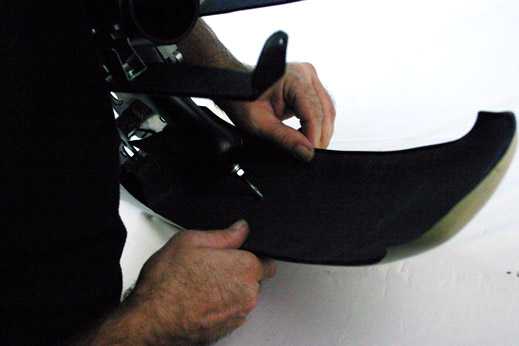
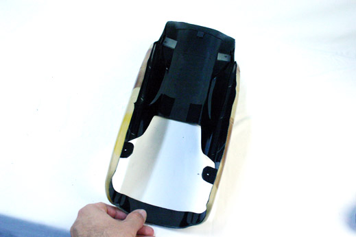
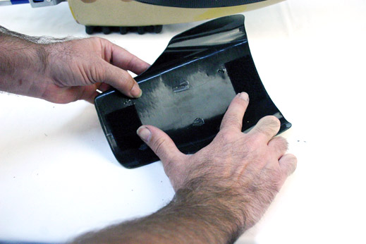
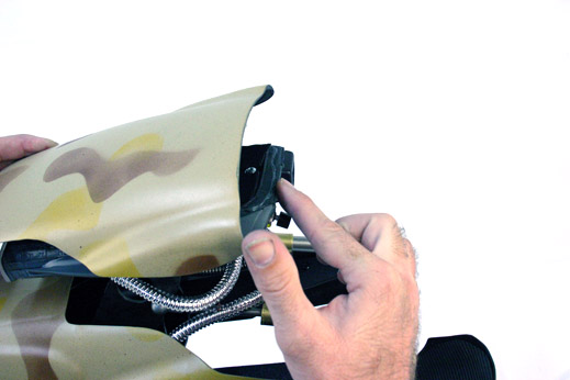
Use Black Putty Tape to form an adhesion ridge 1/4 of an inch away from the edges of the inside of the Bottom Shell. You can see this line of putty in the earlier images when we attached the L-bracket to the Bottom Shell.
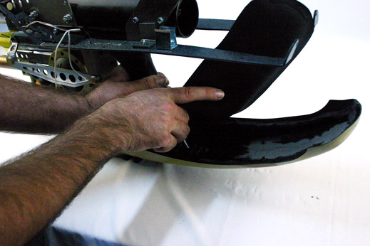
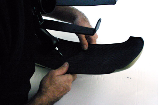
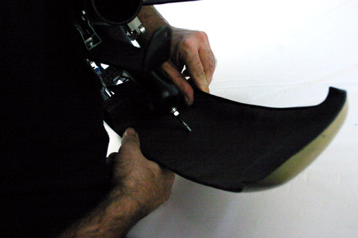
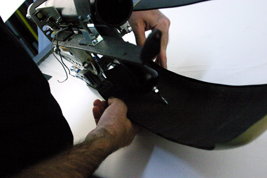
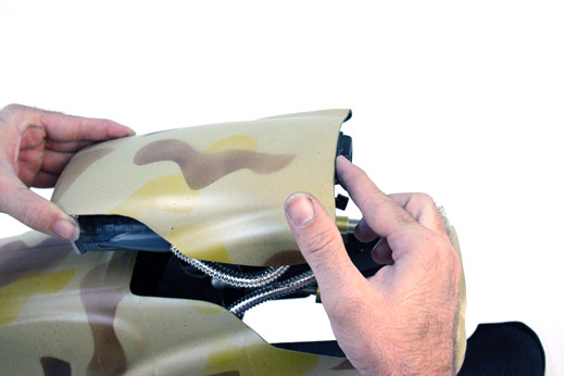
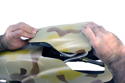
Then, starting at the back of the Shell, press the Floor Mat down onto the putty and work your way forward.
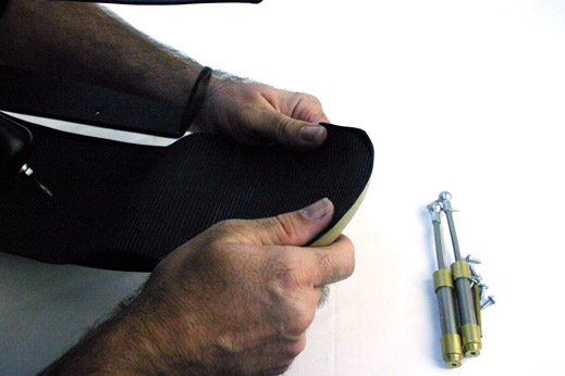

Pneumatic Lift Rods for the Scope
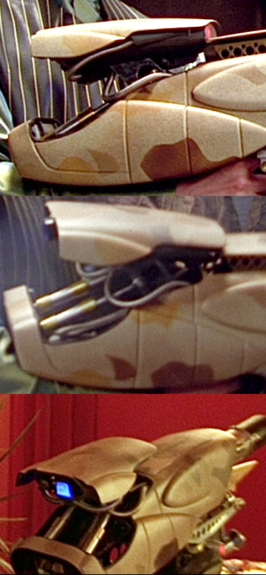
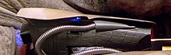
With the mat in place we'll install the Pneumatic Lift Rods for the Scope seen in the various screen captured images above.
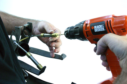
If your parts need to be drilled for attachment of horizontal support posts at the ball joints, do that now. You can drill the bottom of the pneumatic cylinders too, or do it later (as seen below).
Superkrates' Mark III kit should have threaded rods already mounted into the ball joints.
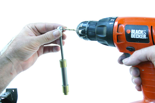
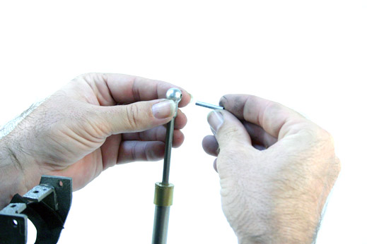
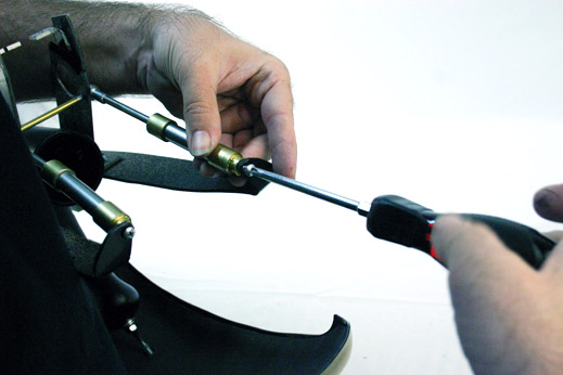
For horizontal support posts, slip in a 1/8 inch aluminium tube into the ball joint, and seal with epoxy or superglue.
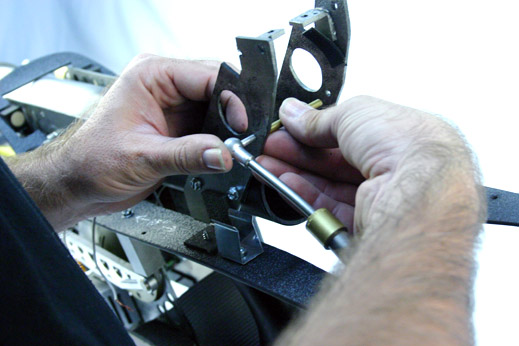
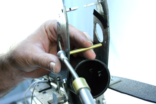
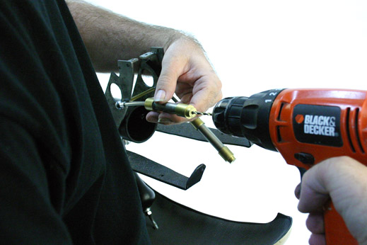
Slide the support rod into the correct hole in the Scope Arm...

... and slide a Brass or Copper tube over the support posts, in-between the Scope Arms.
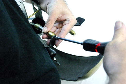
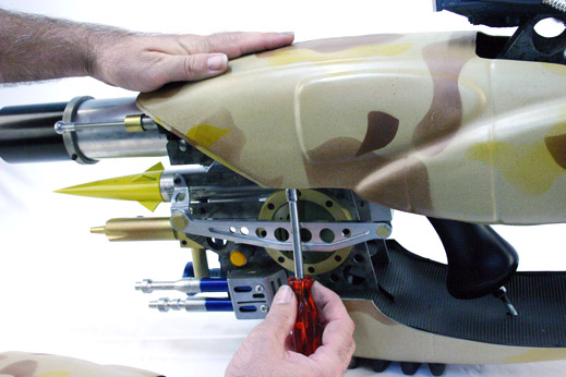
Add the other Pneumatic Rod to the other side of the Scope Arms, and prepare to mount the bottom of the rods to the back of the Horizontal Plate.
Attach the bottom of the Pneumatic Rods with a proper sized screw/bolt that will not overtax and break the Pneumatic Rods.
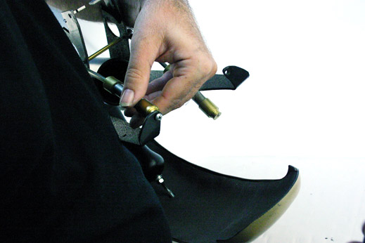
Superkrates Mark III frame has a U-shaped arch built into that frame in the back of the Horizontal Plate. This adds structural integrity to the entire prop.
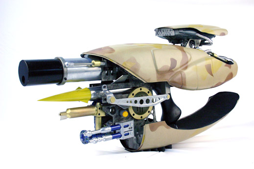
The Scope Body
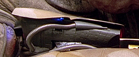
The ZF-1 Scope is cobbled from various off-the-shelf Star Trek model kits, made by the model company Monogram, that were readily available at the time of pre-production on The Fifth Element (1995-1996). Duplicate model kits have been produced over the years by the AMT, ERTL, and Revell model companies.
- The main body of the scope is made the lower engineering section of a Star Trek U.S.S. Voyager model.
- The Two protruding details that adorn the bottom of the Scope are made from parts from a Star Trek Maquis Ship model.
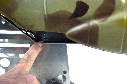
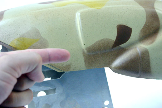
- The Two smooth tear-drop shaped surfaces on the side of the Scope that were made from parts off the Star Trek Kazon Ship.

We thank the prop makers over at therpf.com for their keen eye, and knowledge of the various model kits made over the years, in identifying these model parts. Without their sharing of knowledge, the fans might have never known about these models and their use in this iconic Movie Prop. (major props go out to Zombie Killer and LDR)
The back of the scope is really the front of the model, with the models 'sensor array' blanked out and lights and knobs added in it's place. The monitor screen is approximately a 1.5 inch x 1.5 inch x .75 inch box. We used a 12 mm Push Button Switch to activate everything.
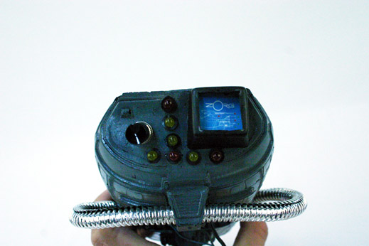
For this particular Superkrates-built replica, the electronics consist of a Bakatronics.com chaser light board and some battery-operated Christmas Lights. The Bakatronics board was rigged to fiber optic wires to light up the 23 light ports seen on the front of the Scope.
The front of the Scope has a Frosted Plastic Plate across the front, diffusing the 23 Red LEDs that animate across the surface. Here is a PDF printable template of the Frosted Plastic Plate.
Note to Webmaster: Show Frosted Plastic Plate template of plate, and add PDF link
And here is a template for a Red Light Holder Plate. I recommend this as a second plate, drilling the needed holes to house the LEDs, then placing the Frosted Plastic Plate in front. Tack glue the Frosted Plastic Plate to the Light Holder Plate along the edges.
Note to Webmaster: Show template of Red Lights Plate, and add PDF link
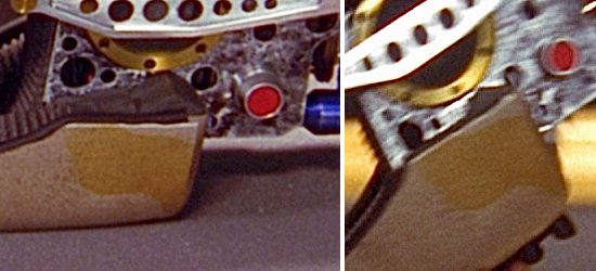
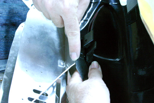
The bottom of the Scope has two additional model parts glued to the bottom of it. Both parts come from a Star Trek "Maquis Ship" model made by AMT/ERTL/Revell/Monogram. Thanks go to "LDR" and "Zombie Killer" over at therpf.com for identifying and sharing their knowledge about these Maquis model parts.
The metal looking Ribbed Hose goes through one of those Maquis parts (which you need to carefully drill a hole through), and ends up attaching to a tear-drop shaped part from a Star Trek Voyager "Kazon Ship" model made by Revell/Monogram (these parts gets glued to the side of the Voyager body). Thanks go to "LDR" for identifying this Kazon model part
There are also two small detail bits that adorn both sides of this tower-like piece that come from the Maquis Ship model also. Thanks to "Zombie Killer" for identifying those tiny detail parts (he get's the title "Most Anal-Retentive Prop Researcher of 2010")
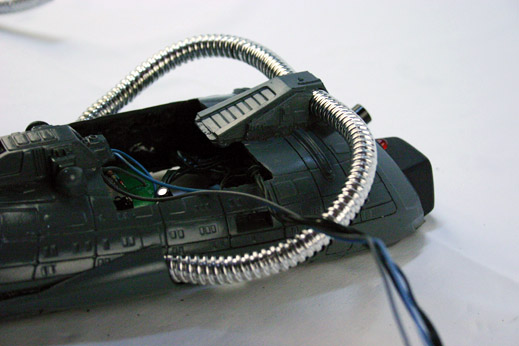
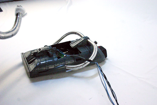
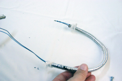
The ribbed hose that was used in this particular ZF-1 Replica is a bit too 'chrome' looking to be fully accurate. If you can afford 1/4 inch OD (outside diameter) Convoluted Stainless Steel Tubing (CSST) (used in industrial vacuum and gas machinery), then get that, but if you need something more affordable, go with a 1/4 inch OD Spring. You need THREE 10-inch-long lengths to finish a ZF-1.
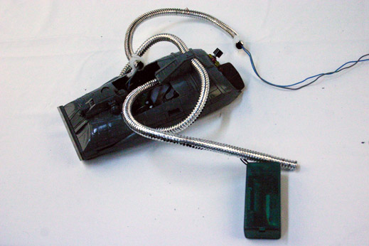
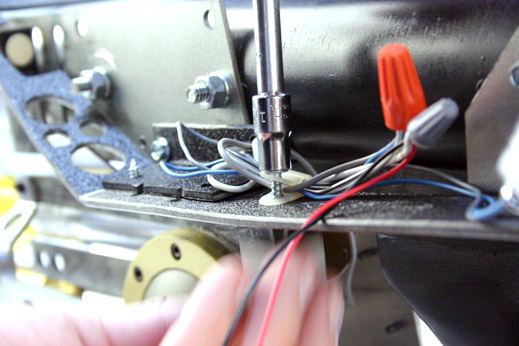
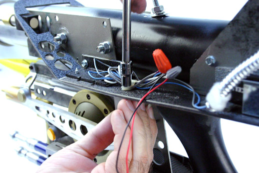
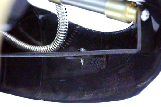
In addition to the Ribbed Tubing that decorates the sides of the scope, two more Ribbed Tubes come out the bottom of the scope and wind themselves down into the body of the ZF-1 itself. We used one of these tubes to wire Battery Power to the Scope Electronics.
We glued velcro tabs to our Ribbed Tubing to hold the tubing in place. The velcro also allows for easy access to the wiring for future maintenance.
Accurate placement of the Ribbed Tubing is to come out the bottom of the Scope, go over and behind the Copper/Brass horizontal support rod...
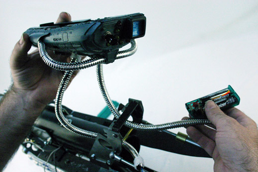
... lay over the Pneumatic Rods and then turn and go forward, into the body of the ZF1.
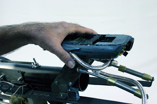
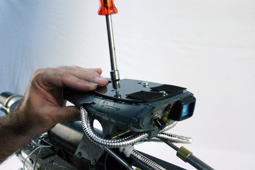
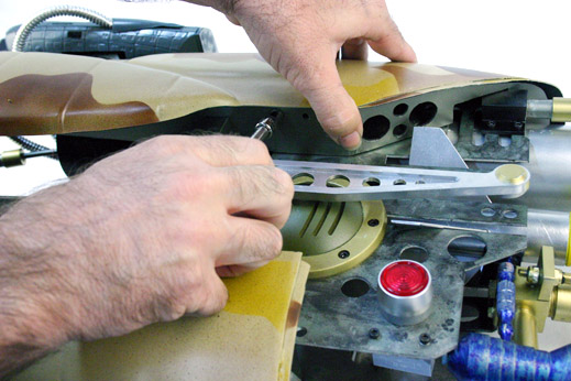
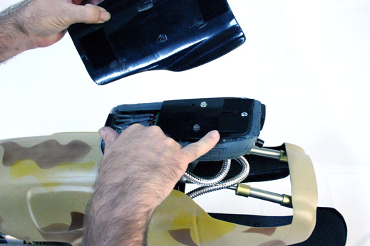
We secure the Scope to the Scope Arms via a mounting plate that goes over the top of the Scope...
Superkrates' Mark III Scope allows for mounting of the Scope Arms to the bottom of the Scope, just inside the cut area.
We secure the mounting plate to the Scope...
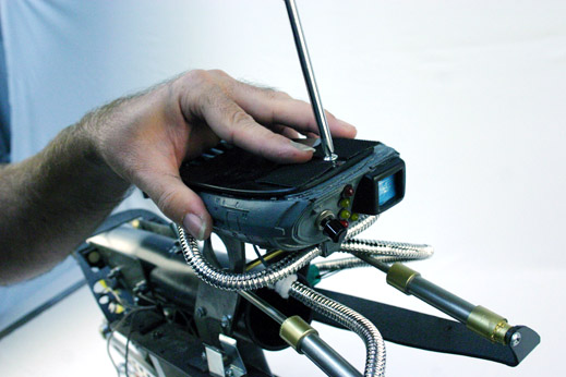
... and the mounting plate to the Scope Arms...
... and we should have a second mounting point here... but we do not. Grrrrrr.
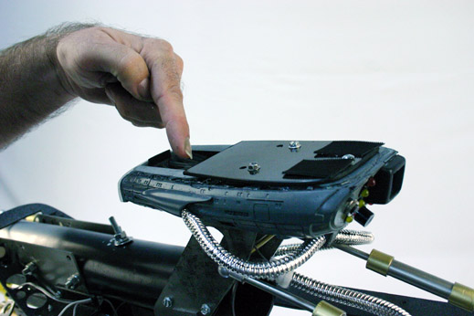
Ultimately the NEW Superkrates Mark III Scope fixes this mounting issue, but if you get a kit that does not allow bottom mounting points on the scope, you know both ways to mount your scope.
"... and Knowing is Half the Battle." - G.I. Joe
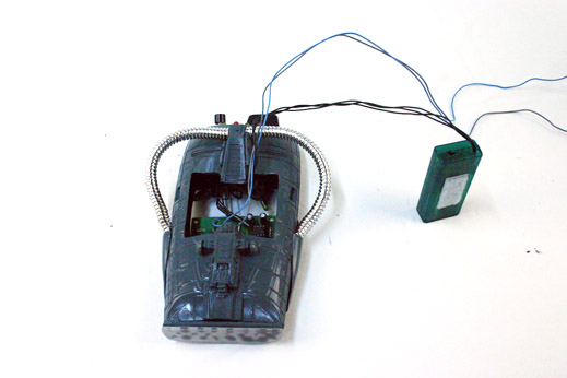
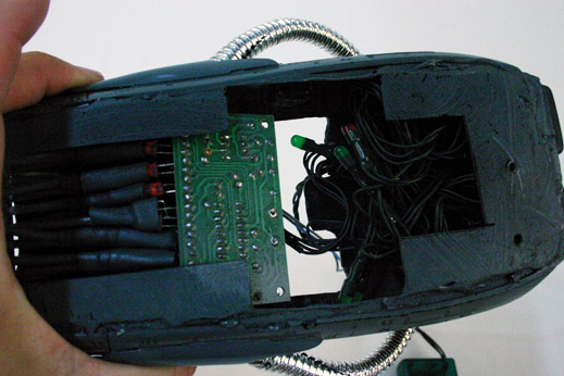
Wiring the Lights/Electronics to the Batteries
Powering the lights and electronics is rather simple. We made sure all of our power requirements were for 9-volts to begin with, so all we have to do it hook up 9-volt batteries to the lights.
Direct Current (DC) is based on Positive (+) and Negative (-) current, so we just need to make sure all our Positive Wires are hooked up to the Positive Terminal, and all the Negative Wires hook up to the Negative Terminal, on the battery.
Usually LED lights have a long metal stem and short metal stem protruding out of the plastic housing, the short stem is universally the Negative lead. If a short stem is not visible, then look at the plastic housing of the LED itself. If there is a flat bevelled edge near one of the leads, then that lead is most likely the negative lead. These are universal tell-tale signs on LEDs, but, exceptions have been known to exist.
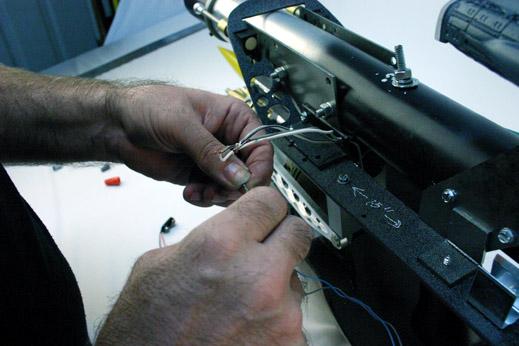
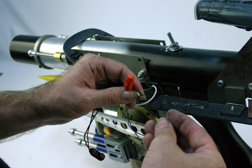
With the ends of the wires stripped, exposing the metal, we'll bunch up the positive wire ends into one group, including the positive battery wire...
... and use a Twist-on wire connector (a.k.a. Wire-Nut) to bind the wires together.
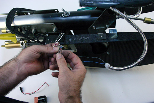
Doing the same to the Negative wires we'll bind those with a different colored Wire-Nut.
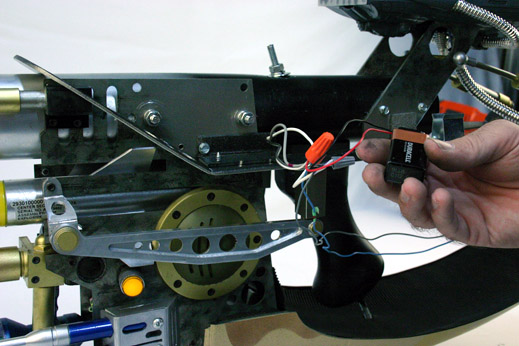
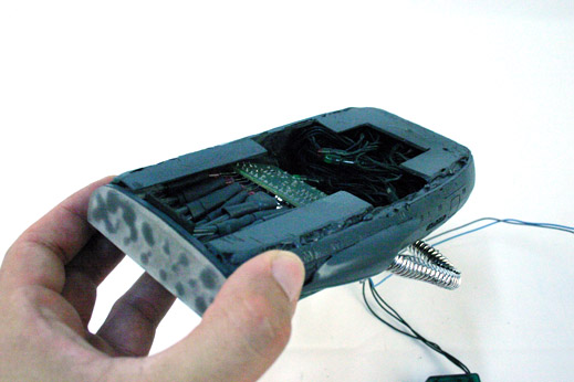
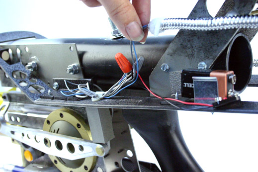
We'll mount a battery holder to the Horizontal Plate, near the Scope arms, to allow for easy access and replacement of the battery, but still be hidden from view when the Upper Shell is mounted to the prop later on.
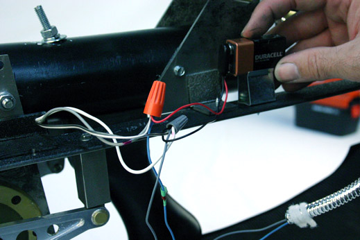
To keep the wires from being a mess, we'll attach a wire holder to the Horizontal Plate too. We used the screw for the Rear Block Bracket to hold the wire holder in place.
Attaching the Upper Shell
Let's attach the Upper Shell to the Horizontal Plate and start really making this replica look like a ZF-1.
You will attach up-to 4 L-brackets to the inside-bottom of the Upper Shell...
Two brackets attach at the front of the shell, one on each side...
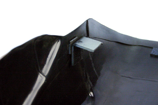
...and One (or Two) brackets go to the back of the shell (near the back of the Scope opening)
Superkrates modified his Mark III Kit to allow a single mounting point on the Back Arch of the Horizontal plate, therefore eliminating the need for two L-brackets in the back.
Attach the two Front L-bracket FIRST
Mount the Front Brackets, check for placement, then mount the Back Bracket/s.
You'll notice in these two images that we had to attach the Front L-brackets twice. The first time we attached them, they were too far forward and the brackets were hitting the Horizontal Plate.
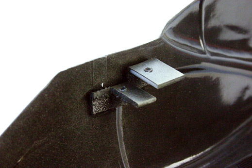
You want to mount the Front L-Brackets about 1.5 inches back from the edge where the shell diagonally slopes upwards, very near the indentions that make the Dart Pod Doors. Remember that the Horizontal Plate is not flush along the wall edge in the sloping area, it's actually tucked up under the lip of the Shell abut 1/8th of an inch.
Animation showing this issue:
The L-Bracket needs room to be mounted to the Upper Shell, so that it never touches the Horizontal plate. It needs to be mounted high enough not to mount flush to the flat area of the Horizontal Plate , but also far enough back not to touch the sloping edge in the front of the Horizontal Plate. Making the L-brackets touch the Horizontal Plates is a very tedious thing to do, so Superkrates feels this 'floating' method is the best solution with minimal hassle.
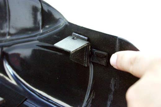
You will use a screw to connect the Horizontal Plate to the L-bracket. As you spin the screw, it will thread through the L-bracket and pull the bracket (and the Upper Shell) down. Eventually the top portion of the Upper Shell will hit the Barrel Shroud Area of the Horizontal Frame. As you continue to torque the screw more, this will secure the Upper Shell tighter against the Barrel Shroud area.
DO NOT OVER TIGHTEN THE SCREW, OR YOU COULD STRIP THE L-BRACKET
With the Front Brackets set, now you can mark the placement of the Back L-Bracket/s. These brackets can mount directly to the Horizontal Plate.
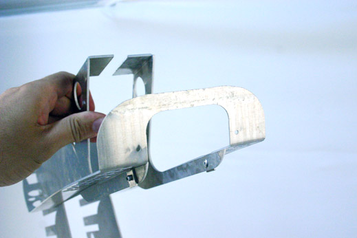
Mounting the Scope Door
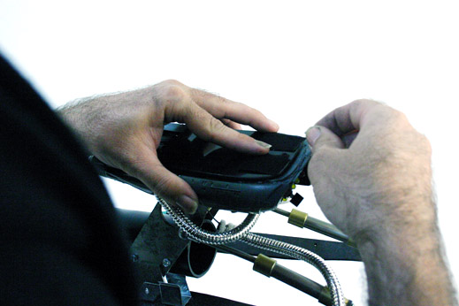
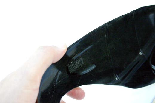
One of the last things to do before your "Fhloston Paradise" ZF-1 is completed is attach the Scope Door to the top of the Scope Body. Superkrates recommends using Industrial Strength sticky-back Velcro to secure the bottom of the Door to the top of the Scope Body. Using velcro allows you to reposition the door later on, just incase the frame of the ZF1 settles-in and adjusts itself or if the ZF-1 is ever dropped.
Velcro tabs....
Velcro tabs...
Checking placement...
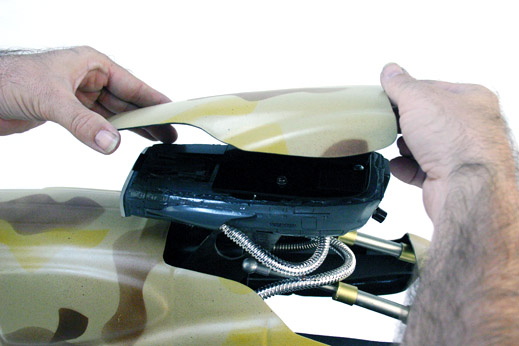
Making sure the Back Door edge will over hang about 1/8th of an inch over the back of the Scope body...
Setting the Door...
Pressing firmly...
YOU ARE DONE!
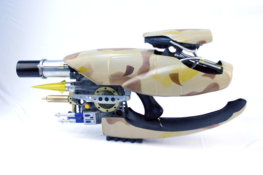
The FINISHED "Fhloston Paradise" ZF-1 replica
-- end
Do You Have Questions or Comments? Contact Us.
©2011 Studio Creations - All Rights Reserved