ZF-1 Assembly Tutorial - Page 2
The Armament Package
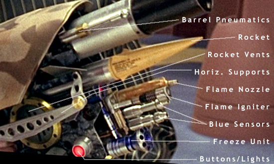
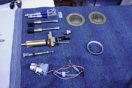
The Armament Package refers to anything that is attached to the Vertical Plates that can be used as a weapon or part of a weapon. The Machine Gun and the Dart Pods would not be part of the Armament Package.
This image shows a few of the parts that make up the Superkrates "Mark III" ZF1 Kit Armament Package...
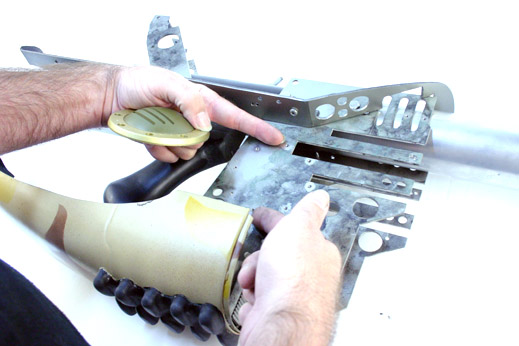
First thing you want to do is attach the Circular Rocket Vents to the sides of the Vertical Plates.
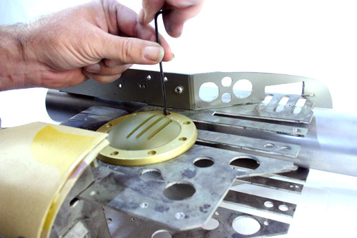
We recommend attaching the top and bottom screws first, getting alignment of the vent perfect, then attaching the rest of the screws. Better to fix two bolt placements now, than 8 bolts later.
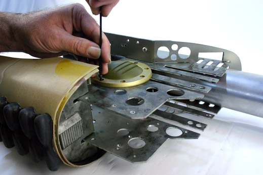
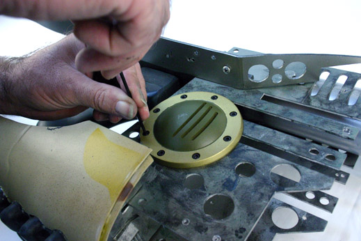
Yellow Light
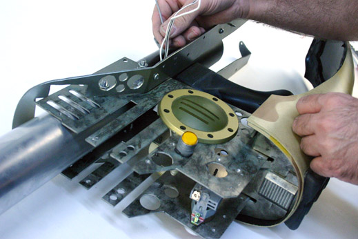
Next we attach the Yellow Lighted Button on the Left Vertical Side Plate.
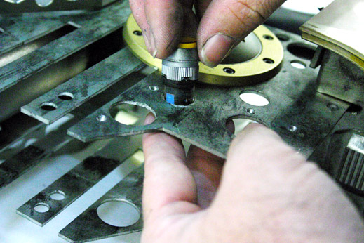
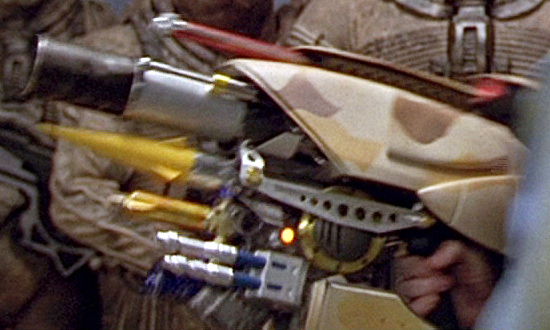
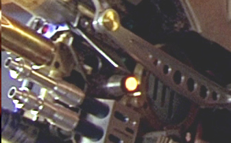
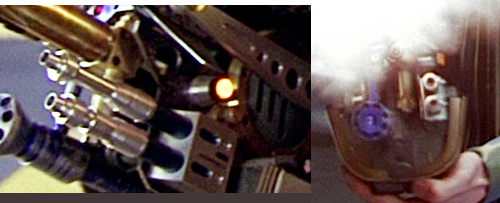
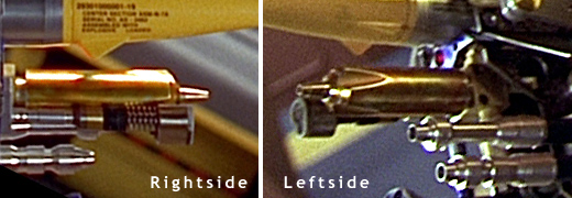
Notice how tall the light is mounted on the side of the Vertical Plate in this screen capture from the movie. Superkrates Mark III kits "should" have this added height to his yellow light parts, but he might not have yet. Check with him and see.
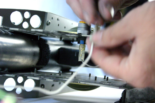
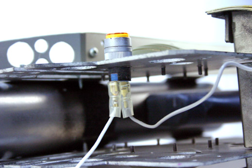
Wire the light for power at this stage.
The Red Button
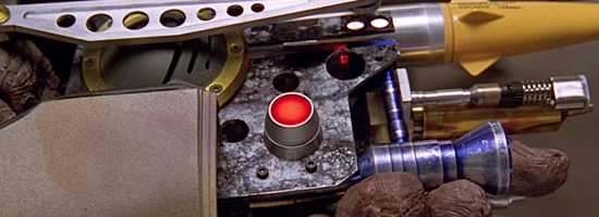
The Red Button. The infamous 'Red Button' has been identified as a Circular Lampholder (25mm diameter) using a 16mm Lens.
Saia-Burgess part numbers: TH454018000 and TH465401000 are the closest looking parts that the prop making community (mainly over at www.therpf.com) have identified for the lamp holder and lens.
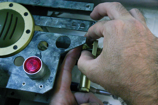
Hold the lamp casing from the front and attach the electronics from the backside of the Right Vertical Plate. Make sure you have wired the lights up and that they work before assembling this together. This light is very difficult to work on once the ZF1 is completed.
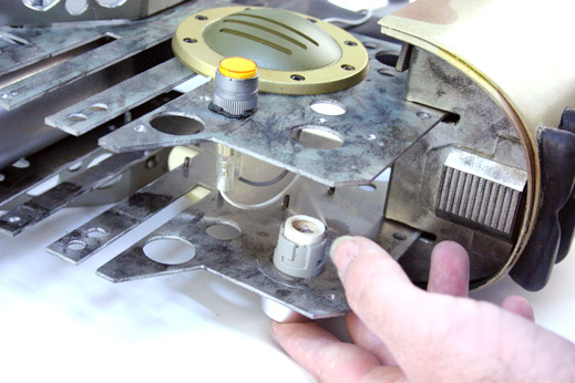
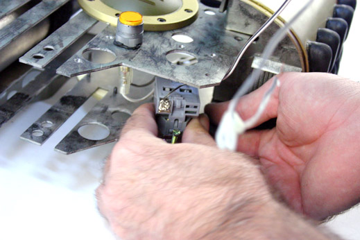
Snug the electronics to the metal frame with the supplied set screws that came with the lamp holder.
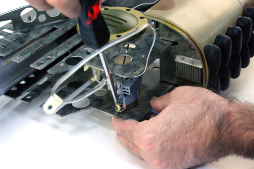
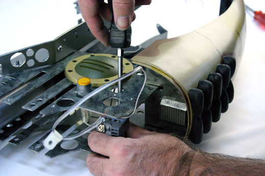
Finally feed all the wires for the Buttons up through the middle of the plates for attachment to the power source later on.
The Blue Sensors
Directly underneath the Yellow Light on the Left Vertical Plate is a metallic colored box with two Blue-and-Chrome protrusions. We call these the Blue Sensors.
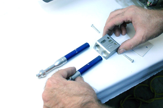
We simply slip one of the sensors into the front holes of the Blue Sensor Box...
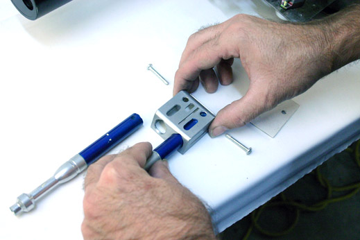
... drill a hole big enough to accomodate the needed set screw, then take the screw and slip it through the box and the hole in the sensor...
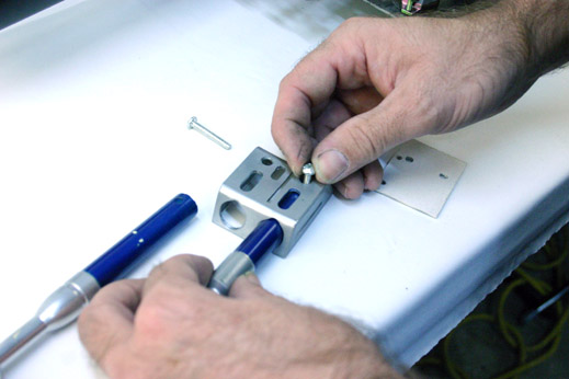
... then line up, drill, and slip-in the next sensor and set screw...
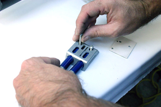
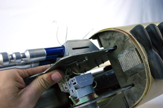
... and add the Backing Plate. (Don't forget to drill the holes for the screws to slip through.)
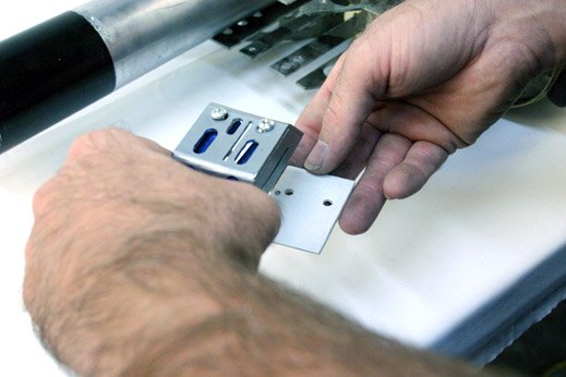
The backing plate is crucial for keeping the Sensors off the wall of the Vertical Plate, which keeps the Sensors pointing straight ahead, and not off to the left, when the screws get tightened down.
Note of Webmaster: Make diagram of Blue Sensor box and how the back plate works.
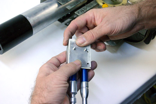
Screwing the sensors in place. (You can die-tap the Vertical Side Plates or use a nut and bolt on the inside wall of the Vertical Side Plate)
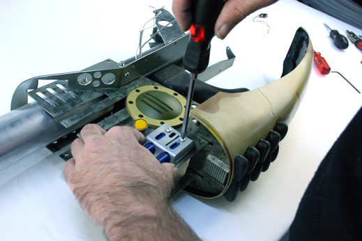
Voila!
Outer Barrel Pneumatic Push Rods
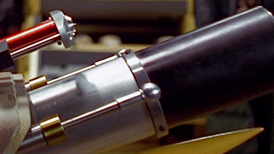
We'll attach the Pneumatic Push Rods to the Outer Barrel now.
If you bought a kit, these will be cast as one piece resin parts. If you hand fabricate your own rods, you'll need to hunt down flat end brass tube caps and 1/4 inch aluminium rods. The black mounting brackets can be fabricated out of metal or plastic.
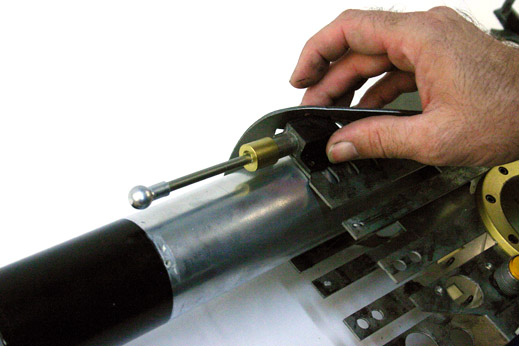
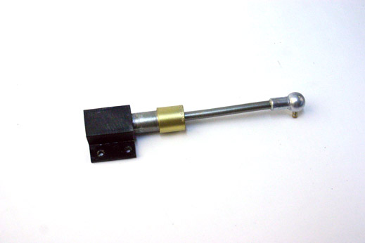
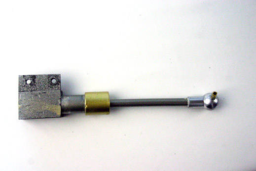
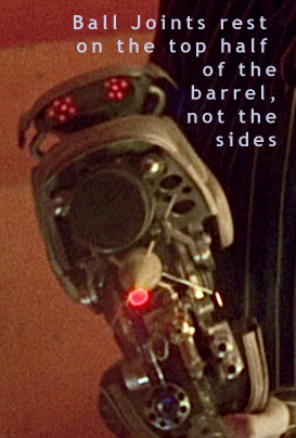
The Barrel Pneumatics do not run perfectly along the side of the barrel as one would think... They actually run along the top 1/3rd of the barrel as seen in this screen captured image from the movie...
Most resin kits do not have the Attachment Rod Hole pre-drilled into the Ball Joint of the Pneumatic Rods. For the Barrel Pneumatic Rods, you need to make sure you drill the hole at a 30 Degree angle from the flat area of the mounting point. This allows for proper placement of the Mounting Rod for attachment to the Barrel Ring.
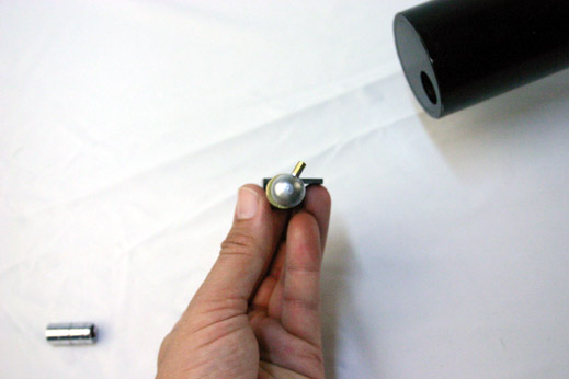
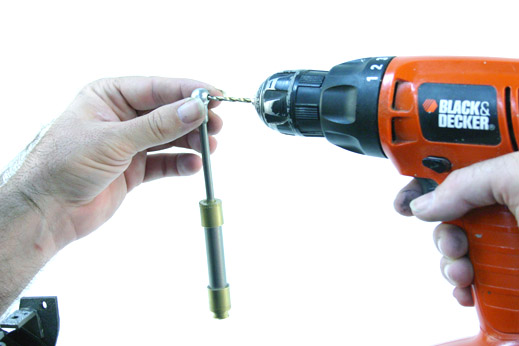
Position the Rod assembly on the side plate...

... slip on the Barrel Ring....
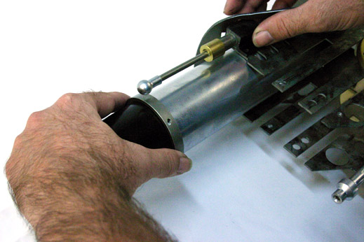
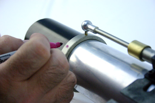
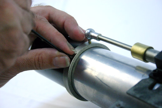
Mark the connection point on the Left side of the Barrel Ring where the two meet-up ...
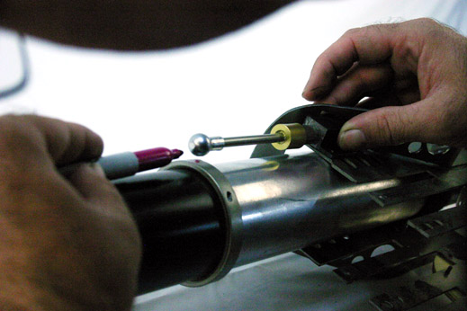
... then drill your holes into the ring and attach the Rod.
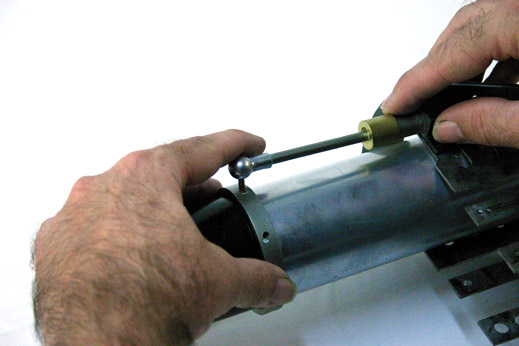
Now you can anchor your Black Bracket to the Side Plate with two Allen Head Bolts.
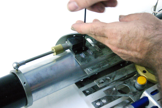
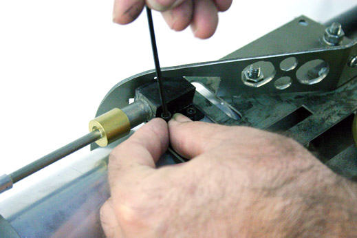
Once the Pneumatics are in place and you are happy with the position of the Barrel Ring, you can mark, drill, and secure the Barrel Ring Set Screw that appears below the Ball Joint on the Barrel Ring. There are one on each side of the Ring and one on the top of the ring (does this mean possibly one of the bottom of the ring as well?), but you can just do one now, while you are working on this side of the prop. The set screws are simple Allen Head Bolts/Screws that keep the ring in place.
The Flame Unit

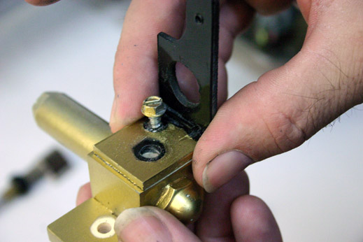
If your Flame Unit comes in pieces (like this kit did), you'll want to attach the Flame Unit Mounting Bracket first (Some kits do not come with this bracket and you might have to fabricate it yourself.)
We use one set screw , set off to the side....
... and add a long screw down the center of everything. The Flame Nozzle will need to be drilled and taped for a secure final connection, and you'll have to drill a hole through the Flame body as well. Be extra careful that you drill everything straight. Borrow the use of a friend's drill press if you can.
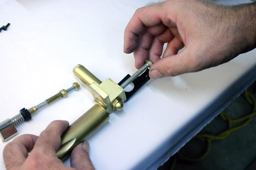
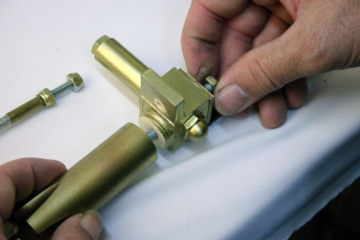
Tighten the screw with a wrench or pliers from the screw head, NOT by twisting the Flame Nozzle.
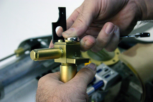
The dimples in the nozzle should be aligned to be on the top and bottom when attached to the ZF1.
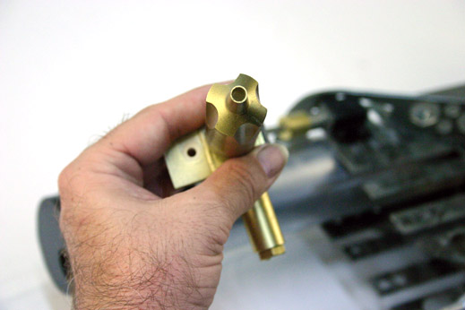
A little known detail that a few people miss is two flush-mounted set screws in the left side of the Flame Body. We drilled and taped these into our final body. The screws do nothing structurally for resin cast replica parts, they are only there for decoration. They probably had a significant purpose on the movie-used prop.
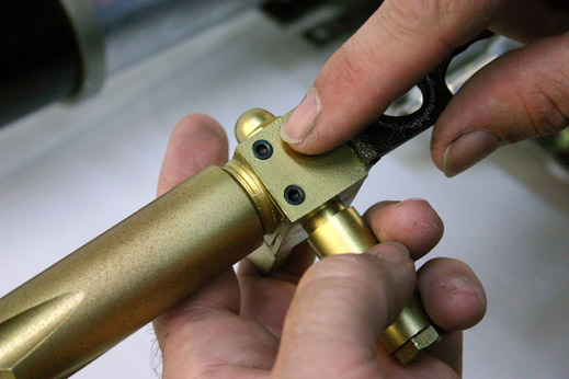
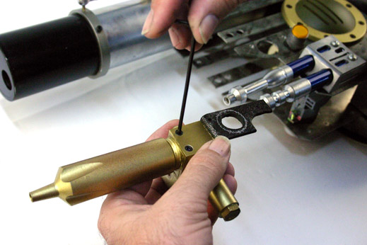
Now we can attach the Flame Unit to the Left Vertical Plate. One screw in front of the circular opening in the plate, one screw behind the opening.
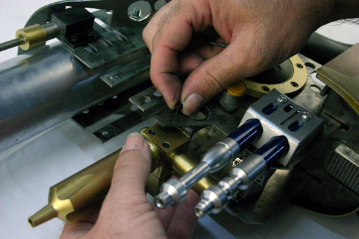
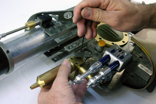
Flame Igniter
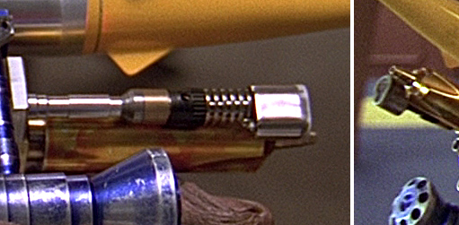
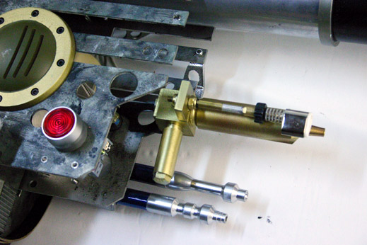
Oh, something we probably should have attached to the Flame Unit before securing the unit to the Vertical Plate: the Flame Igniter. An accurate match to the movie used ignitor is the Blazer GB4001 Stingray Butane Torch, but we lucked out finding a semi-accurate match to the movie part via a "Micro Torch" being sold at our local "Harbor Freight" store. While not 100% accurate, it does have the metal ribs, a black knurled thumb adjuster, and classic tear-drop shape to the nozzle end.
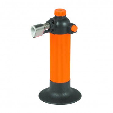
NOTE: We have not purchased a Blazer GB4001 yet, but when we do, we'll post images here.
Using a length of All-Thread and some metal tubing, we extended the length of the Micro Torch and attached it to the Flame Body. One nut on one side of the mounting area....
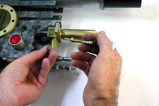
... a second nut on the back side...
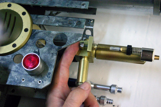
... tightened down into place.
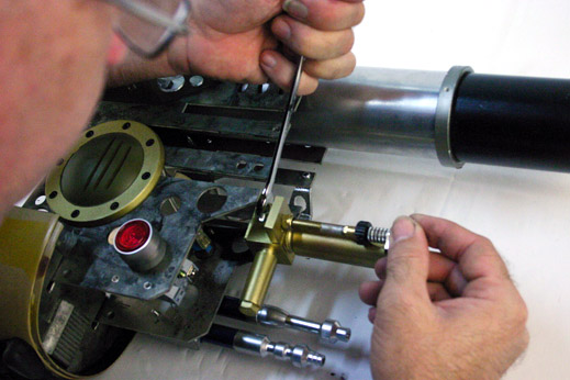
Voila!
Support Brackets
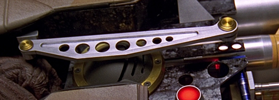
Now we'll attach the aluminium-colored Support Brackets that sit horizontally over the Rocket Vents. From what we can tell, these Support Brackets are faux-brackets, they do not hold up anything or have any real reason other than looking cool.
The each Support Bracket consists of:
- one horizontal frame,
- one rear block bracket,
- and one front multi-angled bracket.
The front and rear brackets should be drilled and mounted to the back side of the horizontal frame.
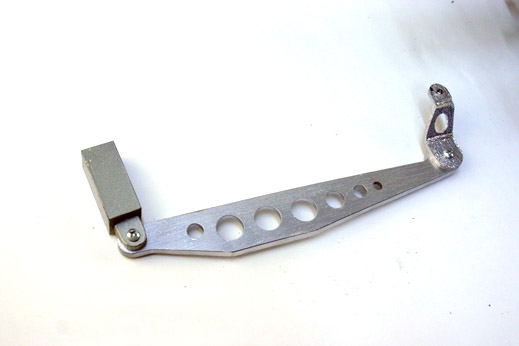
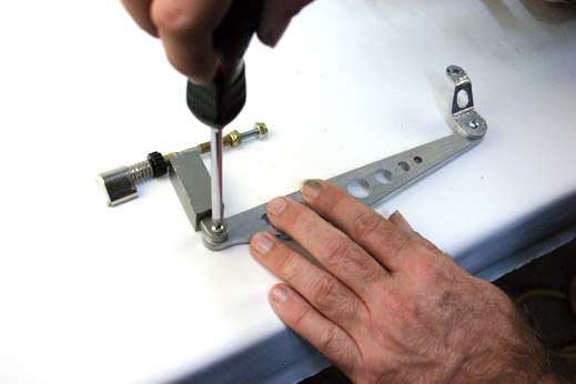
Mount the Front Bracket to the Vertical Plate first. Some frames you will need to custom drill-and-tap the mounting point of the Rear Block Bracket to the Horizontal Plate, so setting the Front Bracket first is a must. (Superkrates Mark III frames have the rear block mounting holes pre drilled)
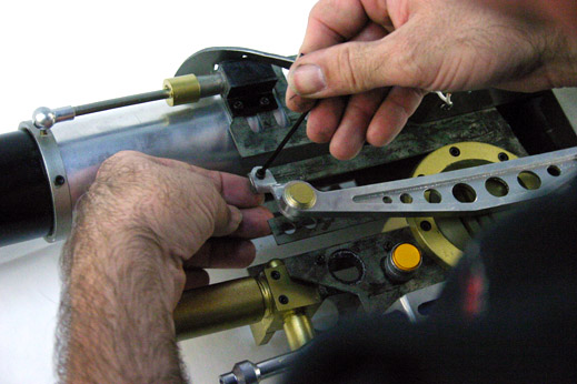
Use an Allen Head Bolt for attaching the Front Bracket to the Vertical Plate. You can drill-and-tap the Vertical Plate for securing the bolt, or use a nut on the opposite side. If you use a nut, remember to use a lock-washer to ensure the nut stays on.
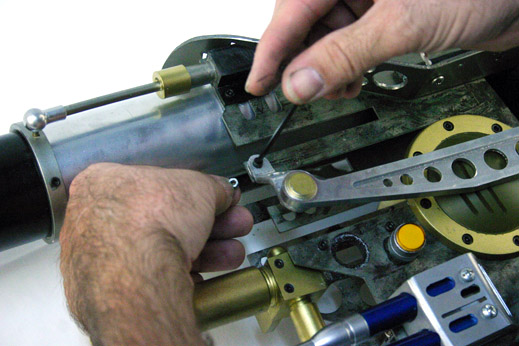
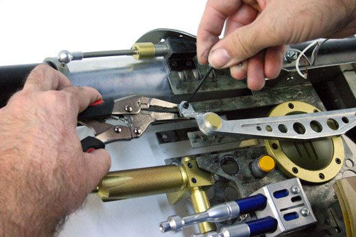
When you have the Front Bracket secure, attach the Rear Block Bracket.
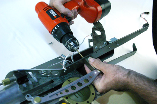
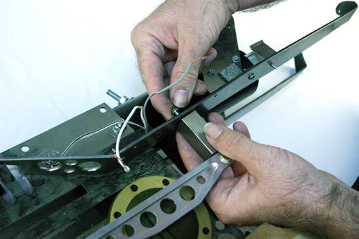
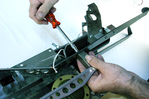
The Rear Block Bracket needs to be positioned so that the Horizontal Frame does not press into the domed surface of the Rocket Vent.
Also, be careful when mounting "resin cast" Horizontal Brackets that you do not mount the Rear bracket twisted, which can stress/warp the Horizontal Frame.
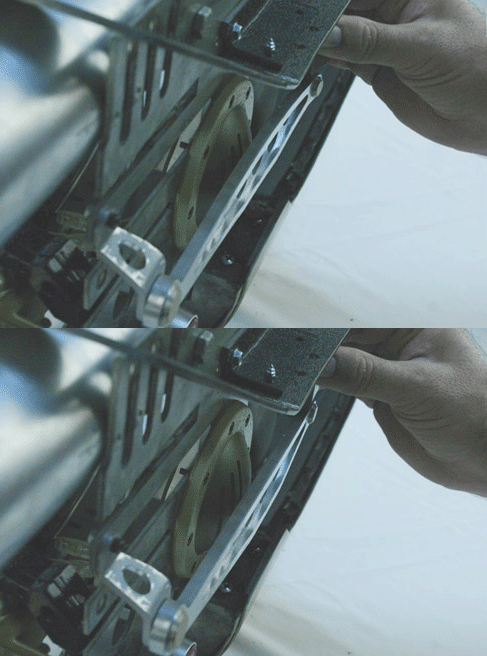
You can mount the right side Support Brackets now, or wait until after the Freeze Nozzle is in place.
!
Continue to:
ZF1 - Assembly: Page 1, Page 3, or Page 4
Do You Have Questions or Comments? Contact Us.
©2011 Studio Creations - All Rights Reserved
