ZF-1 Assembly Tutorial - Page 3
Blue Freeze Nozzle
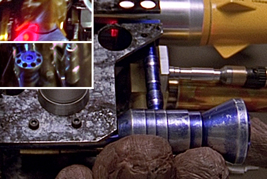
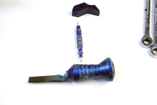
The Blue Freeze Nozzle consists of:
- Freeze Cylinder
- Freeze Mounting Bracket (already attached in photo)
- Vertical Blue Pipe
- Blue Rocket Support Block
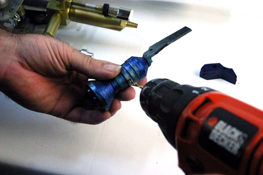
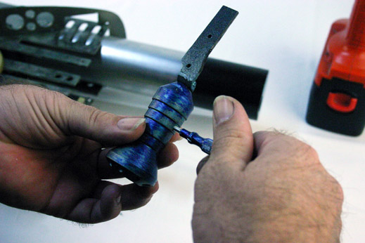
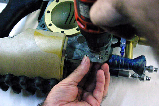
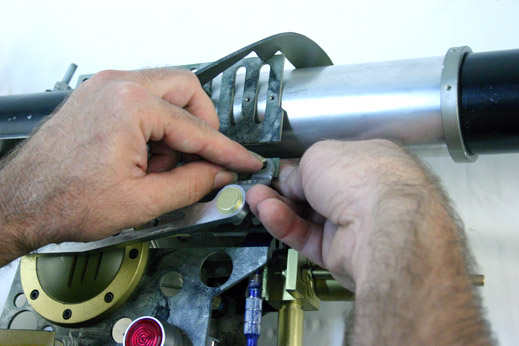
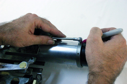
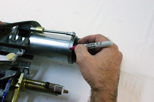
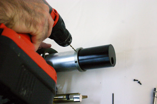
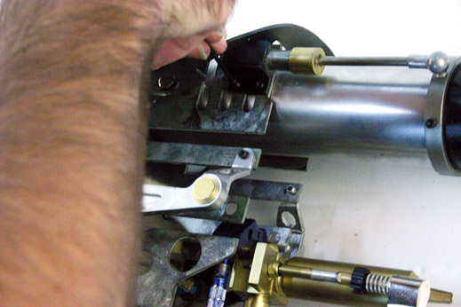
When using the Superkrates "Mark II" ZF1 Kit, you'll want to drill-and-tap the top of the Freeze Cylinder where the Vertical Blue Pipe will mount. This is done on the "middle" ridge of the Cylinder (there are 5 ridges tapering down the length of the cylinder). But ultimately you need to make sure the Vertical Blue Pipe is positioned in the correct place in relation to the Vertical Plates, so check-and-re-check before drilling.
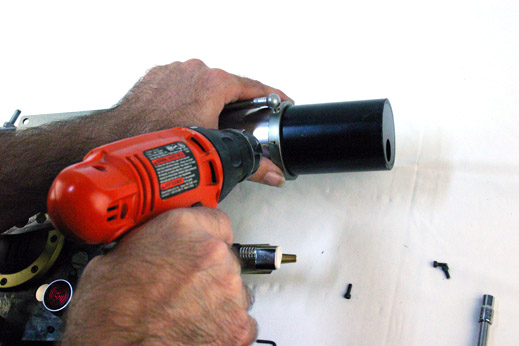
Be sure to drill the hole perfectly straight up and down, or you will be spending some time tweaking and bending the Vertical Pipe to get it to stand straight.
If your Freeze Cylinder did not come with a Freeze Mounting Bracket, you can make one out of a metal L-bracket, or a heated up piece of hard plastic. Most Freeze Cylinders these days have a mounting bracket already attached though.
You can see that the Mounting Bracket uses two Allen Head Bolts to mount the Freeze Frame to the Vertical Plate.
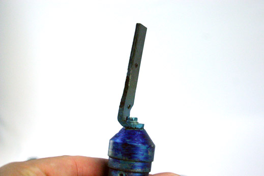
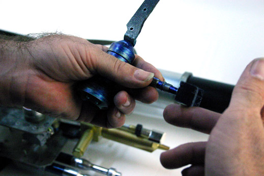
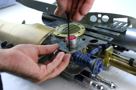
Screw in the Vertical Pipe if you pre-tapped the hole, or secure the Vertical Pipe into the hole with some 2-part Epoxy or Superglue (cyanoacrylate).
Now attach the Blue Rocket Support Block to the top of the Blue Vertical Pipe. Make sure to mount the Block perpendicular to the Freeze Cylinder.
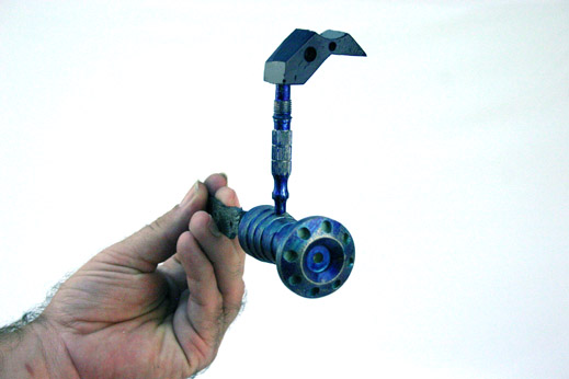
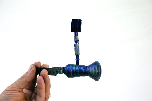
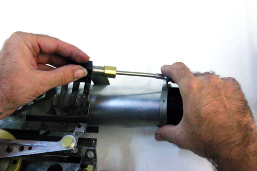
The Freeze Nozzle Unit ready for attachment to the Right Vertical Plate.

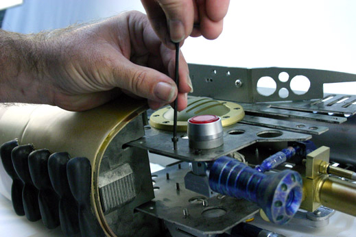
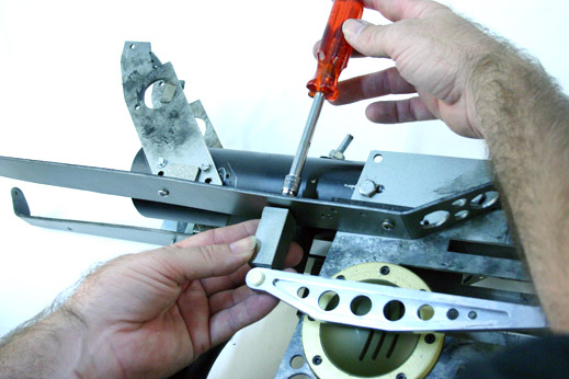
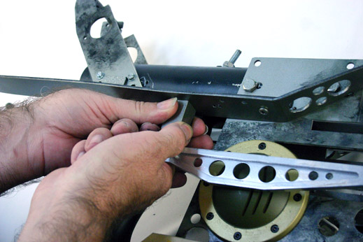
. Using the pre existing mounting holes in the Vertical Side Plate, drill the mounting points in the Freeze Mounting Bracket. Keep in mind the Vertical Blue Pipe and the Blue Rocket Support Block needs to align behind the Flame Nozzle, and flush to the inside edge of the Vertical Plates (use screen shot image at the beginning of this section to compare against).
Add a RED LED light to the inside of the hole in the Blue Rocket Support Block. Secure it from the back side with Hot glue, Super glue, or Epoxy.
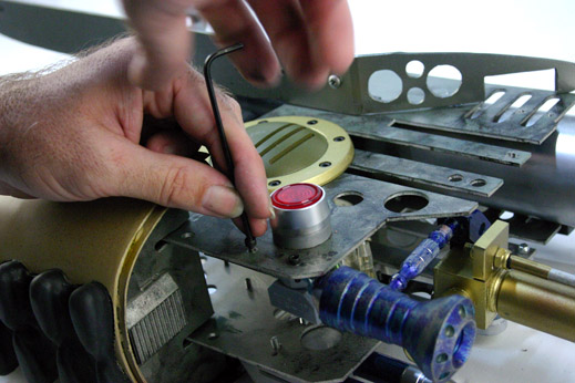
Secure the Mounting Bracket to the Vertical Plate via Black Allen Head Bolts (you can drill-and-Tap the mounting bracket, or use Washers and Bolts).
If you have not mounted the right side Support Brackets, you can do that now.
And we can mount the right side Pneumatic Support Rod for the main barrel too.
Same steps as before.
Mark Ball-Head Joint position with marker...
Mark set screw position...
Drill holes...
Add Allen Head Bolt...
Secure Black Bracket with Allen head Bolts.
The Rocket
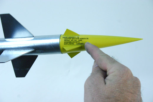
The Rocket used in the movie was fabricated from an ESTES model rocket called the "Bull Pup 12D". The movie version used an aluminium body with tapering edge, attached to the Estes model rocket cone.
As of 2011, you can still buy Estes Bull Pup rockets online and at various local hobby stores, but they are getting harder and harder to find locally. It's amazing that the Rocket is still being offered, as the movie came out in 1997, (and filmed in 1995-1996) so there is at-least 15 years of sales with that one rocket model, which is a testament to the engineering and design appeal of that model rocket!
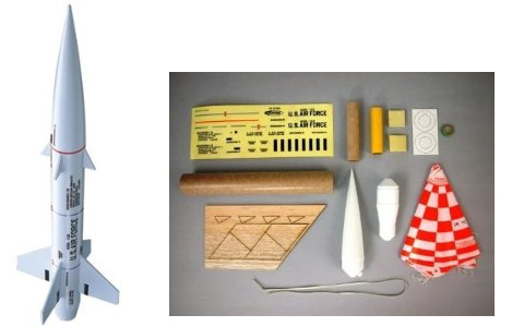
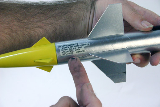
You will need to attach the Larger fins closer to the front of the rocket, than what the Model directions itself call for. This is so that the rocket sits in the ZF-1 properly and does not jut out too far forward, taking away from the look of the finished prop.
Note: Readers, please remind me to take measurements for fin placement and post them here.
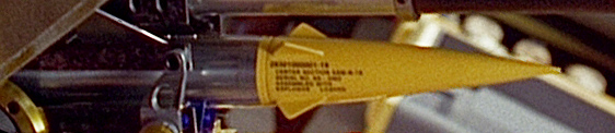
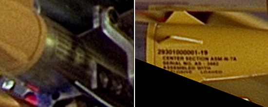
The main reasons why you want to buy the Estes Model rocket is for the official decals. They are clearly visible in the movie, and the text layout of the 2011 rocket decals are practically identical to the 'right side' movie used decal.
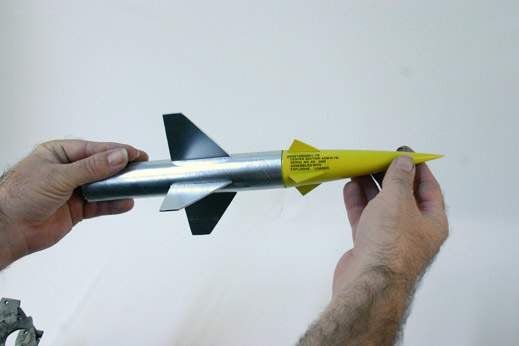
The assembled Rocket will slide up into the front of the ZF1...
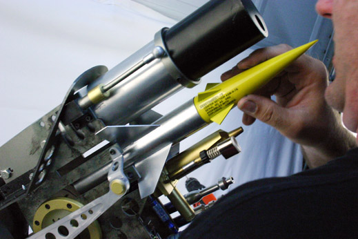
... sliding the fins through the slots in the Vertical Side Plates...
... as seen here...
... and here.
Slide the Rocket all the way to the back of the housing until the large fins cannot go back any further.
Voila!
The assembled ZF-1 at this stage.
!
Continue to:
ZF1 - Assembly: Page 1, Page 2, or Page 4
Do You Have Questions or Comments? Contact Us.
©2011 Studio Creations - All Rights Reserved